This is the multi-page printable view of this section. Click here to print.
OPNsense Config
- 1: VPN Part 1 - Preparation
- 2: VPN Part 2 - Wireguard Instance and Peers
- 3: VPN Part 3 - Interface and Gateway
- 4: VPN Part 4 - Aliases, NAT and Firewall
1 - VPN Part 1 - Preparation
Note
Sadly, the VPN part is one of the first steps, and one of the hardest
There’s Youtube video’s out there if you prefer that can walk you through it all, however, their NAT/Firewall setup will be different than what Synclias needs, so make sure to come back and do Part 3.
Mullvad is used as the example here, however any provider that gives a wireguard configuration file will work pretty much the same way. The main point of note is whether they support IPv6 or not. If this isn’t supported, please see the Advanced section for some suggestions.
Assuming at this point you have a Mullvad account and nothing else, the steps are as follows:
- Part 1 - Preparation
- Get the Config file for your VPN
- Edit the file slighty to put the data in the right format
- Work out the Gateways
- Part 2 - Configuring the VPN on OPNsense:
- Create a Wireguard Instance on OPNsense
- Create a Wireguard Peer on OPNsense
- Confirm the Tunnel is working
- Part 3 - Adding an Interface and Gateway
- Adding an Interface
- Adding Gateways
- Confirm the Gateways work
- Part 4 - Configuring Traffic across the VPN
- Creating the Aliases
- Create NAT rules
- Create the Firewall Rules
Prep Work
Generate your Private Key and Config File
If you don’t have a Wireguard VPN config file, you’ll need to make one. For Mullvad the instructions to create one are as followsl
- Head over to the Mullvad Account Page
- Press the Generate Key button and save the key that appears
- Scroll down to the selection of endpoints
- Pick and endpoint you want to appear from
- Pick a city if offered (Any is fine)
- Pick one of the selected connections (Any is fine)
- Ignore the Content Blocking section
- Click Download File
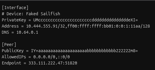
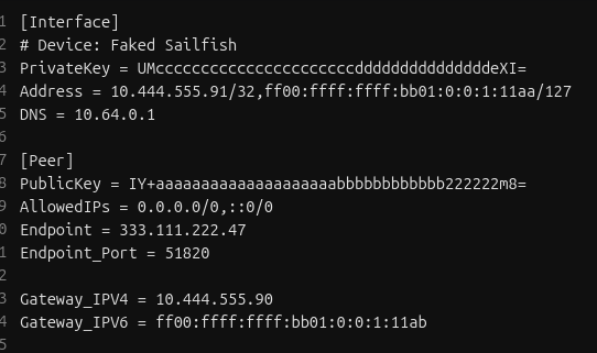
Open the file up and you’ll see settings like this:
Generating all the Info you need
This is the hard part. We’re going to do any working out that we need to do before we start touching the router.
Once this is done, everything else is copy/paste
First, make a copy of the file, we’ll need to edit some things to make the setup easier.
1. Change the Address Line /128 to /127
In the Address line, change /128 at the end of the address line to /127 :
Not doing this step will result in your router not knowing what to do with any traffic you want to send over the VPN
2. Split the Endpoint Line
The endpoint line will contain an IP address and a port, divided by a “:” sign
- Make a new line, and start it with “Endpoint_Port = "
- Copy the port number from the Endpoint line to the new line
- Delete the “:” from the Endpoint line
3. Calculate your Gateway IPs
Your config file may not contain an IPv6 address
Calculating Gateway Examples
Both IPv4 and IPv6 examples will use this line as their base:
Address = 10.444.555.91/32,ff00:ffff:ffff:bb01::1:11aa/127
IPv4 Gateway
Easy one - subtract 1 from the last number in the IPv4 address
Example - IPv4 address (10.444.555.91) gives the Gateway - 10.444.555.90
- Add a line to your config file:
- Gateway_IPV4 = « Your calculated address »
IPv6 Gateway
IPv6 can be a little more complicated, but:
- Take the full address, including the /127 (e.g.ff00:ffff:ffff:bb01::1:11aa/127)
- Find a tool to calculate the subnet (e.g Subnetting Practice.com)
- Paste in the full address and click calculate
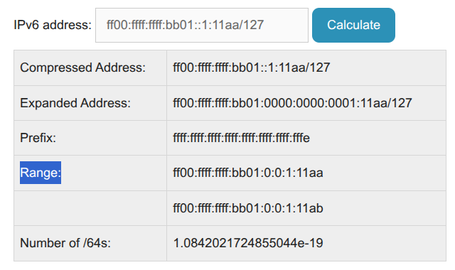
- In the Range section, you’ll see two IP addresses:
- One is the IP address you pasted in (check the last digits here - “11aa”)
- The other is your IPv6 Gateway - example: ff00:ffff:ffff:bb01:0:0:1:11ab
- They may look a little different (extra 0’s and :’s), this is fine
- If you only get one IP in “Range” - did you change the /128 to /127 as required ?
- Add a line to your config file:
- Gateway_IPV6 = « Paste your gateway in here »
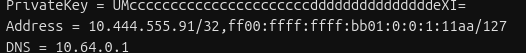
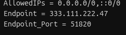
You’ll end with a file that looks like this:
That’s it! The hard part’s over, get ready for some copy/paste
2 - VPN Part 2 - Wireguard Instance and Peers
Configuring the VPN on OPNsense
In this section a Wireguard Instance and Peer will be configured on OPNsense, This essentially forms a virtual cable from your router to VPN.
Create a Wireguard Instance
- Log into OPNsense via the web interface
- In the sections browse to VPN -> Wireguard -> Instances
- Click + to configure a new Instance
- Fill in the details as follows (anything not listed should be left blank)
| Field | Value | Notes |
|---|---|---|
| Name | wg_mullvad_instance | |
| Private Key | Interface.PrivateKey from Wireguard file | |
| Tunnel Address | Interface.Address from Wireguard file | /127, not 128 |
| Disable Routes | Ticked | |
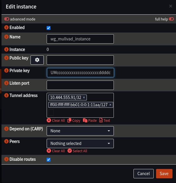 |
- Click Save to close the window, you should see the Instance appear
- Click Apply to load the instance into Wireguard
Create a Wireguard Peer
Here the peer of the VPN will be configured for the instance to connect to.
- Ensure the Web Interface is at VPN -> Wireguard -> Instances
- Select the Peers tab
- Click “+” to configure the peer
- Fill in details as follows:
| Field | Value | Notes |
|---|---|---|
| Name | wg_mullvad_peer | |
| Public Key | Peer.PublicKey from Wireguard file | |
| Allowed IPs | Peer.AllowedIPs from Wireguard file | |
| Endpoint | Endpoint from Wireguard file | e.g. 333.111.222.47 |
| Endpoint Port | Endpoint_Port from Wireguard file | Most likely: 51820 |
| Instance | wg_mullvad_instance | |
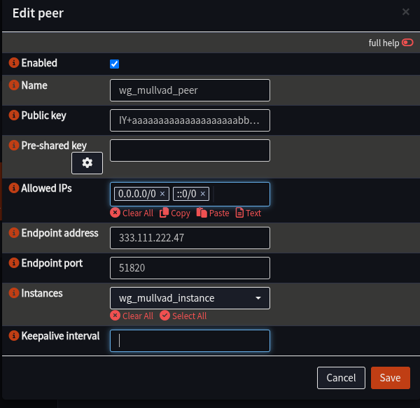 |
- Click Save to close the window
- Click Apply to load the peer into Wireguard
Enable Wireguard and confirm the Tunnel is working
- Navigate to VPN -> Wireguard -> Instances
- Tick the box next to Enable Wireguard
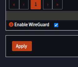
- Click Apply
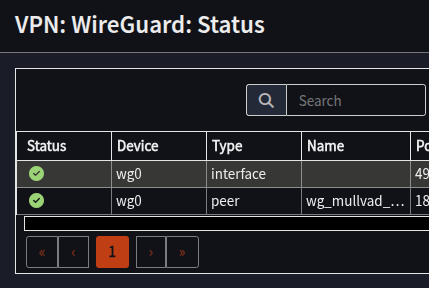
- Navigate to VPN -> Wireguard -> Status
- Confirm Status has green ticks next to the two lines for your peer and an interface with the same Device Name as your peer (e.g. “wg0”, yours may differ)
At this point, the VPN is configured, the tunnel is up, we’ve essentially connected a cable from the router to the VPN provider. It can’t be used yet as the router doesn’t know what to do with your traffic.
Next step is to configure the Interface and Gateways.
Troubleshooting
If you don’t have green ticks:
- Have a look in VPN -> Wireguard -> Log File to see if there is more information as to what’s gone wrong, and double check the instance and peer configuration.
- Restart the Wireguard service:
- Visit Lobby -> Dashboard
- Scroll down to Services
- Locate WireGuard wg_mullvad_instance
- Click Restart next to it
- If you have one green tick and a grey question mark:
- Check your Tunnel Address for the instance has “/127” in it and not “/128”
With all this complete, proceed to Part 3 - Interface and Gateways
3 - VPN Part 3 - Interface and Gateway
This is Part 3 of the VPN configuration.
Following the cable analogy, we now need to add the network card (Interface), and give it an IP address so we can talk to it (Gateway)
This section will:
- Create an Interface for the VPN
- Add Gateway(s) to the Interface to allow traffic routing
Create the Interface
- Navigate to Interfaces -> Assignments
- In the Assign a new Interface section ensure the wg_mullvad_instance is selected
- Enter a Description e.g. - WG_MULLVAD
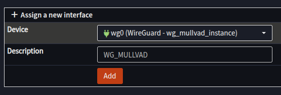
- Click Add
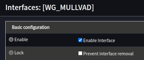
- [WG_MULLVAD] should appear in the left hand menu
- Select the [WG_MULLVAD] interface
- Tick Enable Interface
- Set the MTU and MSS to 1420
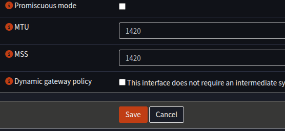
- Click Save
- At the top of the screen a message will appear, click Apply Changes
Creating the IP Gateway(s)
Next, our Gateway IPs will be configured on the new Interface:
- Navigate to Interfaces -> Gateway
- Click + to add a new Gateway
- Fill in the form as follows:
| Field | Value | Notes |
|---|---|---|
| Name | MULL_IPV4_GW | Anything you prefer, but will be needed later |
| Interface | WG_MULLVAD | |
| Address | Gateway_IPV4 from Wireguard config | Just the IP, no “/32” |
| Far Gateway | Checked | |
| Disable Monitoring | Unchecked | |
| Monitoring IP | 4.2.2.2 | Any IP on the internet to test with, suggest 4.2.2.2 |
| Description | Mullvad IPv4 Gateway | Any description you like |
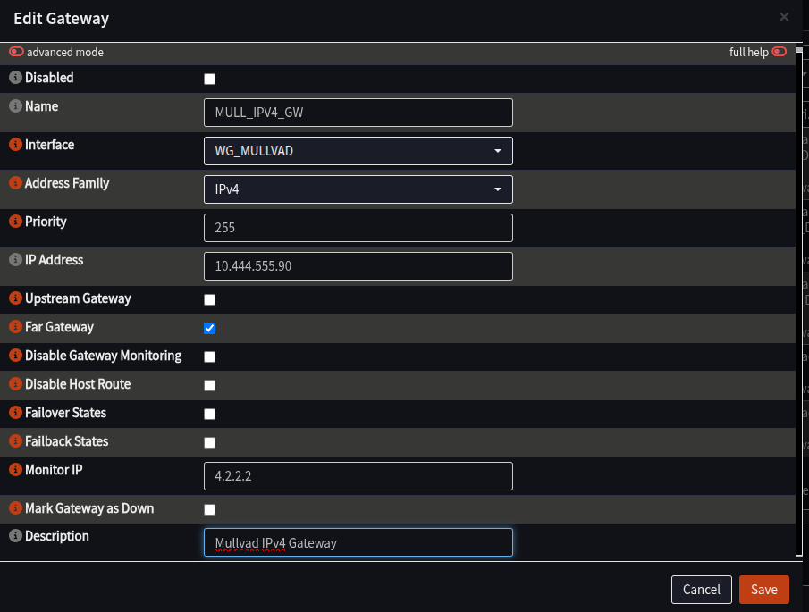
- Click Save
- If you have an IPv6 in your config file, repeat the process to add another gateway, but this time: (Skip this step if there is no IPv6 in your config file)
| Field | Value | Notes |
|---|---|---|
| Name | MULL_IPV6_GW | Same as above, but with IPv6 |
| Interface | WG_MULLVAD | |
| Address Family | IPv6 | |
| Address | Gateway_IPv6 from config file | No /127 or /128, just the IP |
| Far Gateway | Unchecked | |
| Disable Monitoring | Unchecked | |
| Monitor IP | 2001:4860:4860::8888 | Any IPv6 Address, example is Google DNS |
| Description | Mullvad IPv6 Gateway | Any description you like |
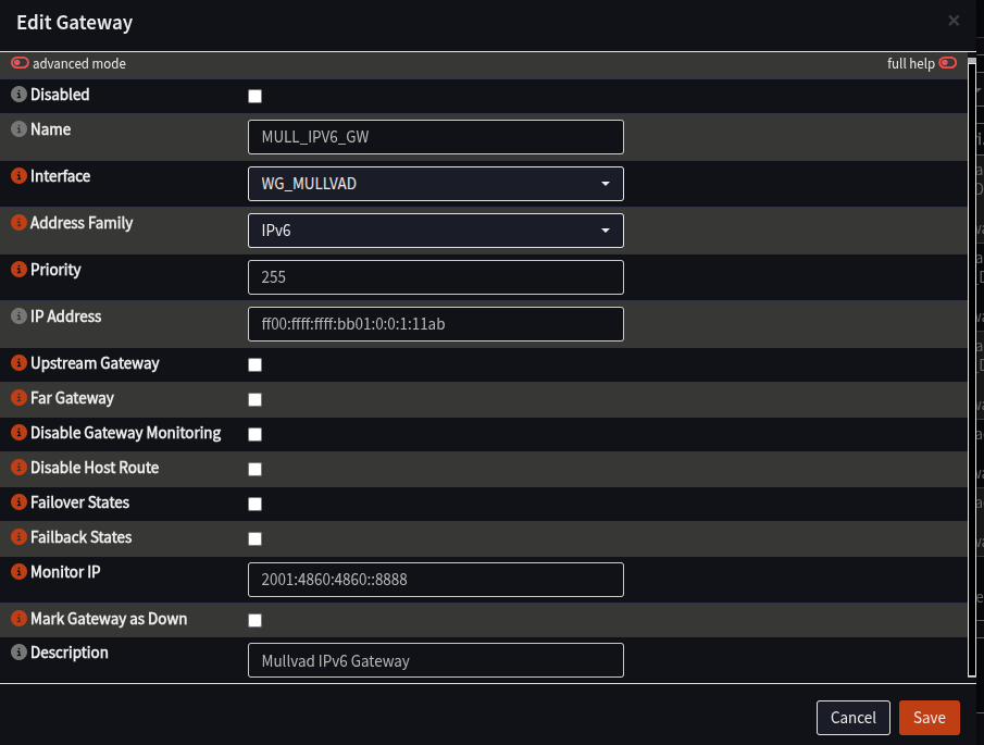
- Click Apply at the bottom of the screen
- Wait at the Overview screen for about about 15-30 seconds to start monitoring
- Click Refresh
- You should see both new Gateways with a green Status, and a time in ms in the “RTT” column:
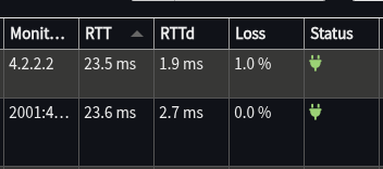
If the Status is fine, this section is complete. The VPN is connected and now has a way to send traffic over it.
The final part is to configure the firewall/NAT to allow and send traffic that way, which takes place in part 4.
4 - VPN Part 4 - Aliases, NAT and Firewall
At this point, the connection is up, there’s an IP address on it, this section will set up rules to allow traffic from internal networks to be sent across the VPN.
It will configure:
- Alias group(s) that will hold the IP/Networks of servers to pass over the VPN
- Outbound NAT rules to modify traffic so it can go over the VPN
- Firewall rules to specify what traffic to configure
Creating the Aliases
- Navigate the Web Interface to Firewall -> Aliases
- Click + to add an Alias
- Add an alias as follows:
| Field | Value | Notes |
|---|---|---|
| Name | VPN_Websites | Can change, but this is highly recommended |
| Type | Networks | |
| Description | VPN_Websites |
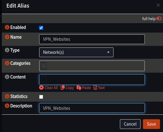
- Click Save
- Click + to add a new Alias for IPv6 if needed:
| Field | Value | Notes |
|---|---|---|
| Name | VPN_Websites_IPv6 | Same comment about spaces as above |
| Type | Networks | |
| Description | VPN_Websites_IPv6 |
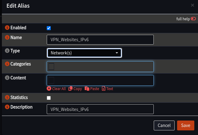
- Click Save
- Click Apply
Creating a NAT Rule
These rules will inspect traffic coming into the router, and if it should be sent over the VPN, it will change the packet to suit to one of the VPN gateways that has been configured
Configure OPNsense to Allow Manual NAT Rules
- Navigate to Firewall -> NAT -> Outbound
- In the Mode section, select Hybrid outbound NAT rule generation
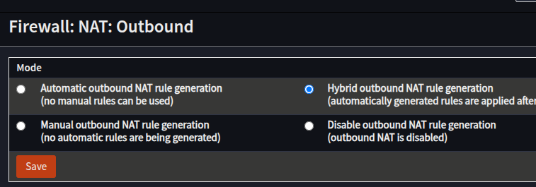
- Click Save
Make the NAT Rules
- Ensue the Web Interface is at Firewall -> NAT -> Outbound
- In the Manual Rules section, click +
- Create a rule for IPv4 as follows:
| Field | Value | Notes |
|---|---|---|
| Interface | WG_MULLVAD | |
| TCP/IP Version | IPv4 | |
| Source Address | Your Internal Network - LAN net/INT net etc | |
| Destination Address | VPN_Websites | |
| Translation/Target | WG_MULLVAD address |
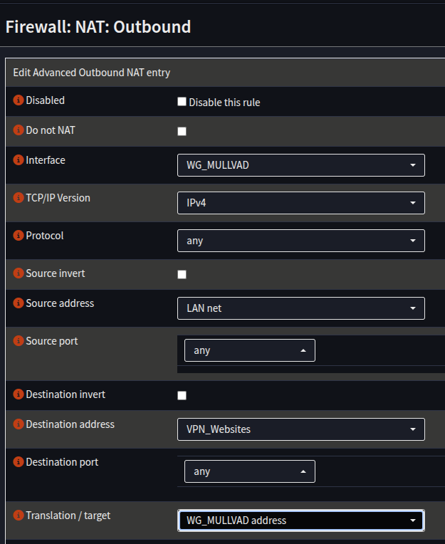
- Click Save
- Create another rule for IPv6 if using IPv6:
| Field | Value |
|---|---|
| Interface | WG_MULLVAD |
| TCP/IP Version | IPv6 |
| Source Address | Your Internal Network - LAN/INT etc |
| Destination Address | VPN_Websites_IPv6 |
| Translation Target | WG_MULLVAD address |
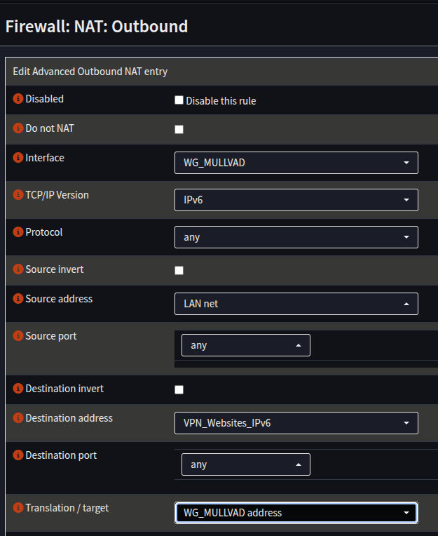 6. Click Save
7. Click Apply
6. Click Save
7. Click Apply
Firewall Rules
If you have the default firewall rules deployed, traffic will be allowed from your LAN out by default, and no configuration will be required.
This section will set up rules to allow all traffic across the VPN, **you may wish to restrict it further, e.g port selection
This will configure a specific rule for the aliases, and assumes nothing else is in place. Please note: you will need to places these rules above any relevant denies, if you are running custom rules, knowledge of how to do this is assumed.
- Navigate to Firewall -> Rules -> LAN
- Click + to add a new rule
- Add a Rule as follows:
| Field | Value | Notes |
|---|---|---|
| Action | Pass | |
| Quick | Checked | |
| Interface | LAN | |
| TCP/IP Version | IPv4 | |
| Source | LAN net | |
| Destination | VPN_Websites | |
| Gateway | MULL_IPV4_GW |
- Click Save
- Repeat the process, but for IPv6:
| Field | Value | Notes |
|---|---|---|
| Action | Pass | |
| Quick | Checked | |
| Interface | LAN | |
| TCP/IP Version | IPv6 | |
| Source | LAN net | |
| Destination | VPN_Websites_IPv6 | |
| Gateway | MULL_IPV6_GW |
- Click Save
- Click Apply
That’s it, all the configuration is done for Synclias networking
Testing Connectivity before using Synclias
If you’d like to test the VPN connectivity, you can route all of your traffic over the VPN :
- Edit the NAT rules to remove the relevant “VPN_Websites” alias and apply your changes.
- Test with whatever “What is my IP address” site you like
- Remember to put the VPN Website alias back in when done!